
Learning more about embedded systems is something I’ve wanted to do for a while. Over the last 20 years all the entry level equipment I’d seen had always been prohibitively expensive or had too steep a learning curve.
In 2012 I started hearing buzz around Arduino, a cheap, open and accessible embedded platform. The Arduino had substantially lowered the barrier-to-entry in both cost and simplicity. It has also been around long enough now to have built a mature community around it, you can find help on pretty much anything you want to do.
As a way to learn about the Arduino and some basic component-level electronics I set myself up with a new project. The goal was to modernise a retro clock radio so that it can display the room temperature and humidity, as well as the time. As the old clock radio was not great at keeping time (and I’m too lazy to press buttons to correct it), I wanted to wirelessly connect to it so that I can sync the time with something more reliable.
Design considerations
The original unit is a classic Phillips AJ3150. In 1989 the US publication Clock Radio Monthly magazine awarded it the “Best designed AM/FM clock radio under $20”. One clock radio aficionado even features it in his museum. Because of the elegantly classic façade of the clock radio and the history behind it, I wanted to remain true to its heritage and keep the original exterior untouched as much as possible. Not so concerned about the inside of the unit, the only part I planned on keeping was the LED display.
The first task was to figure out how the LED display works. Naively I thought each 7-segment digit could be controlled quite simply by supplying a current to the segment I wanted to light up, and that it’d be a simple matter of each part of each number either being on or off. The reality was far from this. After failing to figure out how the display works via trial and error, I started hunting around for some information on how it works. This led me to a very helpful data-sheet detailing everything about the display and indicated just how far wrong I was about how to use it.
As I found out, the display used some pretty crude multiplexing; only half the display can be lit up at any one time. In order to give the impression that the full display is on, each half of the display would need to be switched on and off at least 25 times per second.
Keeping time on the unit was another thing that I’d assumed would be pretty simple, and initially it was. The first attempt involved setting the time on the Arduino, and incrementing a counter every second. This works for a short time, but over a couple of days the time drifted by around 1 second per minute. Not ideal for an appliance whose primary function is time-keeping.
The solution was to ‘outsource’ the time keeping to a Real Time Clock (RTC). These are controllers that run on a separate circuit and also have a battery backup. Instead of incrementing counters every clock cycle, the Arduino queries the RTC whenever it wants to know what the time is.
In order to set the time, I needed some sort of interface to the Arduino. The clock radio had numerous switches and buttons on it, but I’ve never liked having to hit a button to increment the minute counter, sometimes up to 59 times, to get to the correct value.
Price-wise, WiFi and Xbee were a bit of overkill for the job at hand, so I went with Bluetooth.
Bluetooth controllers are available for about $12, and they provide a wireless serial communications channel that is supported by most laptops and mobile phones. I was then able to build an Android app that could connect to the clock and synchronise the time with my phone.
As an extra gimmick, I wanted to be able to monitor the temperature and humidity in my bedroom. This turned out to be one of the easier parts of the project thanks to the relatively user-friendly DHT11 chip. The DHT11 is a reasonably cheap unit (shipped from China for $2.30) that can be polled to get the temperature or humidity. It has some smarts built into it already to smooth the readings, which is a major issue with some of the basic temperature and humidity sensors.
Given that an Arduino Nano only has 13 digital I/O pins and I needed 16 just for the display (31 segments displayed in 2 phases), I’d need a way to get one pin to be able to do more than one thing.
By converting a serial signal to parallel signal, a multiplexer (or shift register) effectively allows you to control 8 outputs using just 3 pins on the Arduino (read more here). So using two 8-bit shift registers, I was able to get the 16 outputs I needed using just 6 pins on the Arduino.
The LED display worked by only showing half the required segments at any one time. In order to get the full image, each half of the display needs to be toggled on and off at least 25 times per second (so it doesn’t appear to flicker). This would normally be reasonably trivial and simple to program on the Arduino using 2 outputs and just toggling them either on or off, providing power to either half of the display (two positive and common ground terminal). But for reasons I don’t understand, the display needed to be ground switched, i.e. the display uses a common positive and two ground terminals.
This led me down the path of learning about the fundamental building block of modern technology, the transistor. Very basically, transistors have three terminals (base, collector and emitter). Current comes in through the collector and it leaves via the emitter. The switching is done by supplying a small current to the base, which will either open or close the connection between collector and emitter. Using two transistors, I was able to control which of the ground terminals were closed (allowing current to flow) at very high speed.

Building
Like any rebuild, the first step was to gut the interior. As I had no experience with working with plastics, I decided the best approach would be to delicately cut away the internal framework with some sharp wire cutters. It did work for a while, but it was frustratingly slow. So I turned to power tools. The multi-purpose renovator tool turned out to be more than up to the job, stripping out the interior in a matter of minutes. It was like using a bulldozer to demolish a sand-castle, very efficient and quite satisfying.
Next step was to figure out how to put the unit together. The entire prototype looked as though it could fit entirely inside the case if laid out well. So to save the trouble of rebuilding the project on a circuit board, this is the approach I took. With some innovative and liberal use of double-sided and gaffer tape the assembly came together quite well.

Software
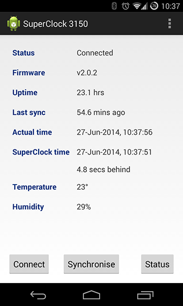
I had written an Android app that could connect to the clock (via Bluetooth) and synchronise the clock with the phone time. It could also fetch the temperature and humidity values from the sensors and display some diagnostics (up-time, time-drift, last sync time). But somehow, I lost the code. One complete rewrite a year later I had a reasonably stable Android app with all the functionality of the original.
Communication between the Android app and the SuperClock was done via Bluetooth serial port profile (SPP). A simple plain-text protocol was devised to allow getting basic info from the clock, and allowing the app to set the clock time. Once the Bluetooth communication layer is up and running, the app can read and write to the socket using standard Java input and output streams.
The code is available on GitHub.
Parts list
| Part | Link | Price |
| Arduino Nano | http://arduino.cc/en/Main/ArduinoBoardNano | $7 |
| Phillips Clock Radio (AJ3150) | http://www.radiomuseum.org/r/philips_aj315000aj_31500.html | Priceless |
| Real Time Clock (DS1307) | https://learn.adafruit.com/ds1307-real-time-clock-breakout-board-kit | $1.50 |
| Bluetooth interface (HC-06) | http://www.mikrokopter.de/ucwiki/en/HC-06 | $6 |
| Temperature and humidity sensor (DHT11) | http://www.adafruit.com/products/386 | $2.30 |
| 2 small breadboards | https://www.sparkfun.com/products/12043 | $0.30 ea |
| Breadboard wires | http://www.adafruit.com/products/153 | Negligible |
| Multiplexer (74HC595N) | http://www.nxp.com/products/logic/shift_registers/74HC595N.html | $0.20 |
| Transistor (2N2222 NPN) | http://en.wikipedia.org/wiki/2N2222 | $0.08 |
Lessons learned
The SuperClock 3150 has been in production for well over a year. There have been no issues at all with the reliability of the hardware. There have been some issues with loose wires when the unit takes a fall, but that is a symptom of wiring the internals using jumper wires and breadboards. Soldering the components to a circuit board would solve this issue.
There is a minor issue with flickering and temporary dimming of the display. If I were to build a future version, I’d use one Arduino to drive the display and another to handle I/O (separation of concerns, MVC, etc.). As good as the Arduino hardware is, it is important to remember that they are low-cost low-powered single-threaded devices. Each unit should be used to do one thing, and do it well.
Pretty much every electrical component ever has some sort of data-sheet detailing everything about how it works in explicit detail. All components will have a code printed somewhere on them (from individual transistors to integrated components like the LED display), it’s simply a matter of typing this into Google and rummaging through the results. With most popular components you should even be able to find trivial examples of how to use it with an Arduino.
